Vacuum Vessel Architecture
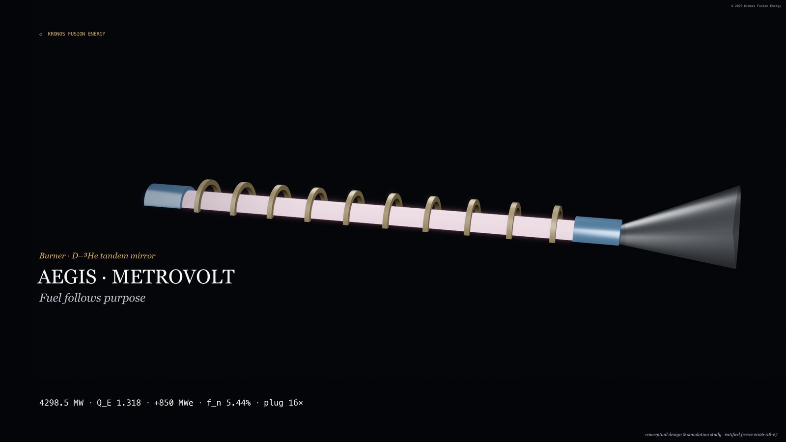
The vacuum vessel is the long, straight envelope that holds the plasma volume under high vacuum and carries the ports for fuel, heating, and diagnostics.
The vacuum vessel of the burner is a linear pressure boundary — a straight tube spanning the plugs, throats, central cell, and expanders — that maintains the high vacuum the plasma requires. Unlike a toroidal vessel it has open ends that transition into the expander and DEC tanks, making it a through-axis structure rather than a closed shell.
The vessel must hold vacuum against atmospheric pressure, provide clean surfaces so impurities do not enter the plasma, carry the many ports for beams, RF, fueling, pumping, and diagnostics, and route neutron and radiation shielding around all of them. Its length and straightness are set by the central-cell burn volume plus the plug and expander sections at each end.
Vessel requirements
- Maintain high vacuum over a long, straight volume
- Provide clean, low-outgassing internal surfaces
- Carry ports for heating, fueling, pumping, and diagnostics
- Integrate first-wall and shielding structures
- Transition smoothly into the expander and DEC tanks
- Withstand atmospheric load over a long unsupported span
The vessel wall must carry atmospheric pressure over its full length without buckling, which for a long straight tube means either wall thickness or intermediate support rings. Those rings compete for the same axial space as ports and shielding, so the wall structure and the port map are designed together.
Ports and penetrations
Every port is a break in the shielding and a potential vacuum leak, so penetrations are minimized and shielded individually. Beam ducts, RF launchers, pumping ports, and diagnostic windows are laid out to avoid direct neutron streaming paths to occupied areas. The vessel's port map is one of the constraints that shapes the machine's overall footprint and shielding design.
All figures are design and validation values for a machine not yet built.