🎧 Prefer to listen? Open the audiobook
The Magnets: The High-Field Path
A magnetic field is the only wall in the universe that can touch a star and not melt. Everything in this book comes back to that one truth, and to one number: the strength of the field. Not the plasma temperature, not the fuel, not the cleverness of the control system — those all matter, and they each get their own chapter — but the field is the lever that makes the rest of it small enough to build and cheap enough to matter. Compact fusion is, at bottom, a magnet problem. Solve the magnet and the machine shrinks; fail to solve it and the machine stays the size of a cathedral and the price of a moon program. To hold a hundred-million-degree plasma in a cage of pure force is one of the strangest feats of engineering ever attempted — we are forging fields no small machine was ever meant to hold. So before we talk about breeders and burners as reactors, it is worth stopping on the thing that lets them be compact at all: a ribbon of ceramic superconductor, a few hundredths of a millimetre thick, wound into coils that hold a field strong enough to bend the path of a fusion product — and yet, at the end of the analysis, limited not by how much field the material can carry but by how hard the winding is being pulled apart while it carries it.
That last sentence is the whole chapter. The field is not the hard part anymore. The stress is.
Why field is the lever
Start with the physics, because the physics is unforgiving and it is also, in this one respect, generous. The rate at which a magnetically confined plasma produces fusion power, for a machine of a given size, scales roughly as the fourth power of the magnetic field. Double the field and, at fixed size, you get sixteen times the fusion power density. That is not a marginal edge. That is the difference between a reactor you can put on an industrial site and one that only a nation-state can contemplate.
The reason is a short chain of proportions. Fusion power density goes as the square of the plasma pressure. The pressure a magnetic field can hold is set by the magnetic pressure, which goes as the square of the field. Put those together — power density proportional to pressure squared, pressure proportional to field squared — and you land on power density proportional to field to the fourth. Written plainly:
Double the field and, at the same size, a fusion machine makes sixteen times the power. That single scaling is why the entire compact-fusion program lives or dies on magnets.
This is why the field, and only the field, buys you compactness. You can chase the same fusion power by making the machine enormous — that has always been the other road, and it is the road that gave fusion its reputation for being forever thirty years away. Or you can raise the field and let the fourth-power scaling do the shrinking for you. The second road is the one that only opened recently, and it opened because of a material.
What REBCO tape is, and why it changed the game
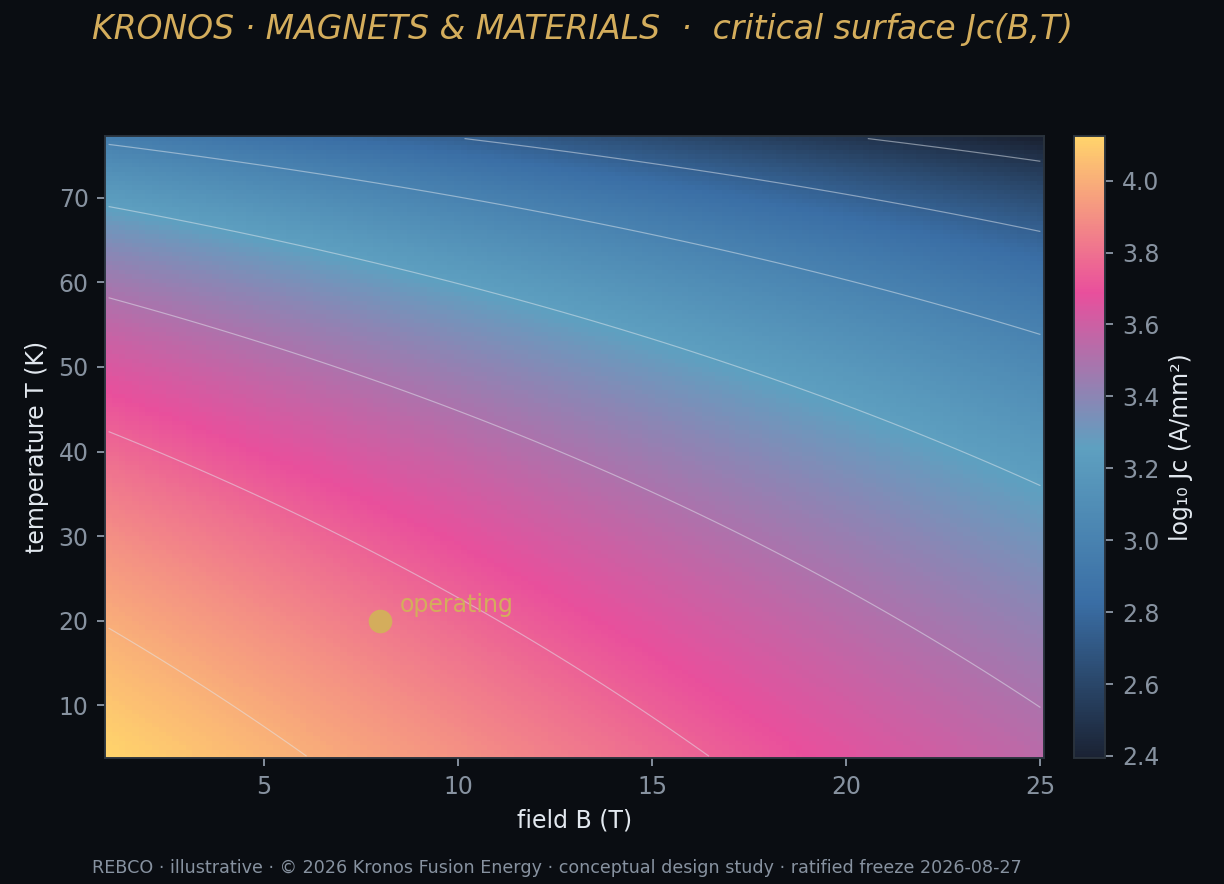
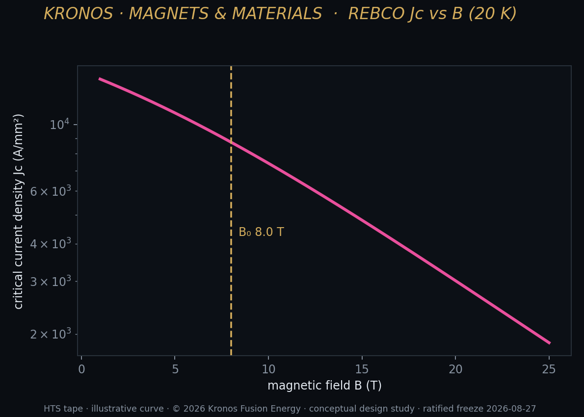
For most of fusion's history the superconductors available to magnet builders were the low-temperature ones — niobium-titanium and niobium-tin — and they came with a hard ceiling. Push them much past the field they were rated for, or warm them much above the temperature of liquid helium, and they stop superconducting. They quench. In practice that capped the deliverable field on a large fusion coil at somewhere around eight to thirteen tesla, and it is no accident that the great tokamak designs of the last century were built around fields in exactly that band — and were, in consequence, enormous.
Then a material arrived that broke the ceiling, and with it the whole prospect of fusion changed in the span of a single decade. It is a coated conductor built around a rare-earth barium copper oxide — REBCO, for short, a high-temperature superconductor. It is not a wire in the way you picture a wire. It is a tape: a thin metal ribbon on which the superconducting compound is grown as an epitaxial film only a few microns thick, sandwiched between buffer layers, a silver cap, and a copper stabiliser. The active superconductor is a sliver. Most of the tape, by thickness, is structure and protection.
What makes it revolutionary is where it keeps working. REBCO carries supercurrent at fields above twenty tesla and at temperatures above twenty kelvin — a regime flatly inaccessible to the older superconductors. Laboratory magnets built from it have already reached, on the public record, a direct-current field of 32.35 tesla from an all-superconducting magnet, and 45.5 tesla from a small no-insulation test coil. A fusion-relevant, large-bore toroidal-field model coil has been demonstrated at roughly twenty tesla. These are not projections. These are magnets that have been energised and measured by others, and they are the reason a compact fusion machine is now a serious engineering proposition rather than a physicist's daydream. When people say the last decade "changed everything" for fusion, this tape is most of what they mean.
Kronos does not manufacture this tape, and I want to be exact about that from the outset because it governs how you should read every number in this chapter. We have coated no conductor and energised no coil. Every conductor figure here is public data — an independent group's measurement, a design target, or an inference from the published literature — applied to our winding by our analysis. The value we add is not a fabricated sample. It is the analysis of how a real conductor behaves when you wind it into the two very specific coils our two machines demand. That discipline — public data in, honest verdict out, nothing claimed as measured that was not — is the spine of the whole thing.
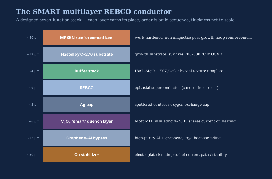
The company's magnet physicists, who between them carry a long career in high-field magnet design, built the conductor concept as a seven-layer "strain-first" stack. The point of the stack is not the superconductor, which is a sliver of the whole; it is everything around the superconductor that keeps it from breaking:
| Layer (build order) | ~Thickness | Role |
|---|---|---|
| Work-hardened superalloy reinforcement | ~40 µm | Post-growth hoop reinforcement (cryogenic yield above 2 GPa) |
| Textured substrate + oxide buffer | ~16 µm | Survives film growth; templates the crystal texture |
| REBCO film | ~9 µm | The epitaxial superconductor — carries the current |
| Silver cap | ~3 µm | Contact and oxygen-exchange layer |
| "Smart" quench interlayer (vanadium oxide) | ~6 µm | Insulating when cold, current-sharing when hot |
| Metal bypass stabiliser | ~12 µm | Cryogenic heat-spreading path |
| Copper stabiliser | ~50 µm | Main parallel current path and stability |
The philosophy in that word strain-first is the tell. The stack is not designed to carry the most current. It is designed to keep the brittle ceramic film from ever being stretched past the point where it breaks. And that priority — protect the film from strain, not chase the field — is exactly the right one, because of what the analysis found next.
I want to be equally plain about the two claims in that stack that our own analysis knocked down, because the honesty of a design study is measured by what it retracts. The metal bypass was originally posited as a high-purity aluminium conductor meant to beat copper's magnetoresistance above twenty-five tesla. A proper analysis of how resistance grows with field says otherwise: aluminium's apparent edge comes entirely from its higher purity, not from any insensitivity to field, and that edge evaporates once you degrade the purity with the reinforcement a structural conductor needs. So we report the aluminium-bypass advantage as unsupported at the operating field — copper is adequate, and we say so. The second retraction is subtler: the work-hardened superalloy that makes such a fine reinforcement cannot also serve as the substrate the REBCO film is grown on, because epitaxial growth demands a different, textured base. It is defensible only as a post-growth reinforcement lamination — which is standard practice — and we correct the record rather than let the tidier version stand. Neither retraction changes the verdict; both are the difference between a conductor concept you can trust and a brochure.
The field is not the limit. The strain is.
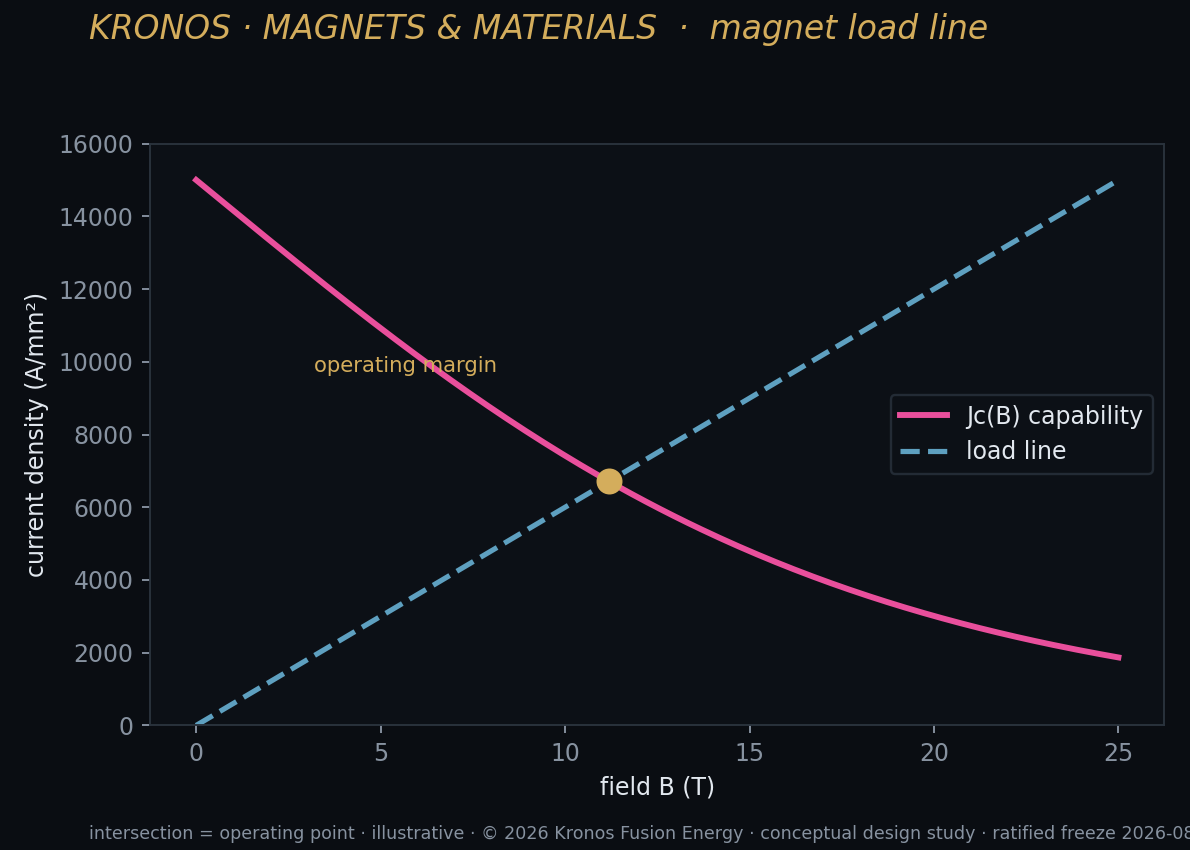
Here is the fact that reorganises everything. REBCO's own upper critical field — the field at which the material itself stops superconducting — exceeds one hundred tesla at liquid-helium temperature. A thirty-five-tesla operating point, which is already beyond anything a large fusion coil has ever been asked to deliver, sits at roughly one-third of that material limit. So on the question everyone instinctively asks first — can the superconductor take the field? — the answer is an emphatic yes, with enormous headroom.
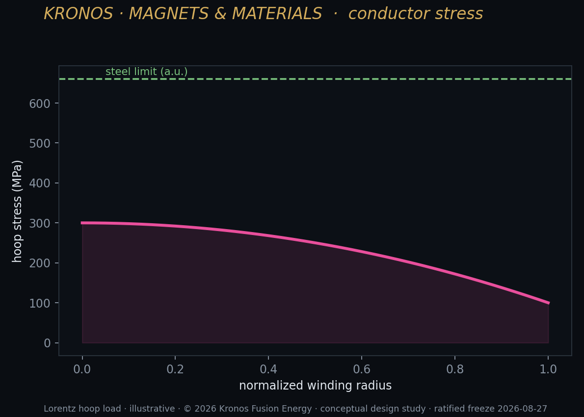
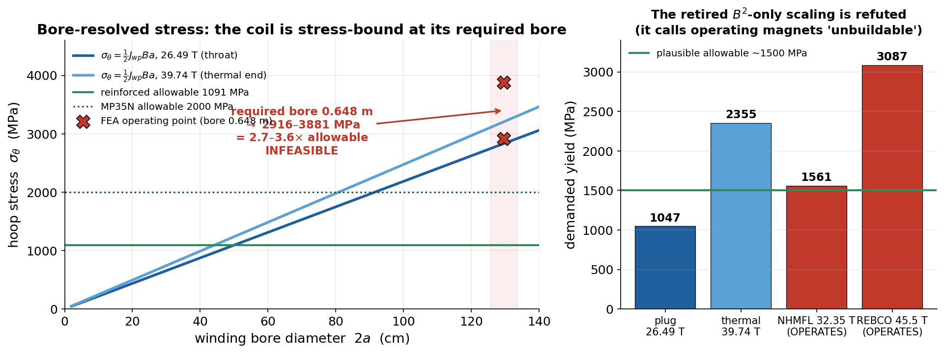
That headroom is a trap, because it invites you to think field is the game. It is not. The thing that actually limits a high-field fusion coil is mechanical. A current-carrying conductor sitting in a magnetic field feels a force — the Lorentz force — and in a coil that force pulls the winding radially outward, trying to burst it open like the hoop of a barrel under pressure. The stress that results is the winding's hoop stress, and REBCO has a cruel property here: the ceramic film delaminates and its current-carrying capacity degrades irreversibly once it is strained past roughly four-tenths of one percent in tension. Not fatigued over time. Not degraded gracefully. Strained past that point once, and the tape is permanently worse. The engineering cap we hold to is a 0.40 percent irreversible-strain limit, and it is the hard wall of the entire design.
So the design problem is not "how much field can the tape carry." It is "how hard is the winding being pulled apart to make that field, and does that exceed what the structure and the ceramic can survive." The quantity that answers it is the hoop stress, and for a solenoidal winding it takes a clean, standard form worth putting in a box:
σ_θ ≈ ½ · J_wp · B · a
In words: the hoop stress in the winding (σ_θ) is roughly one-half the product of three things — the winding-pack current density (J_wp, how much current you are pushing through each square metre of the coil cross-section), the magnetic field (B), and the coil's bore radius (a, how big the hole in the middle of the coil is). This is textbook thick-solenoid mechanics; we did not invent it. We put it at the centre of the design because of one feature that most discussions of high-field magnets quietly skip: the dependence on bore radius, a.
That single term is the hinge of this whole chapter. A tempting shortcut in the field is to scale magnet difficulty by field alone — by B squared — as if a strong field were intrinsically hard. It is not. A field-only scaling has no bore in it, and therefore cannot tell a small coil from a large one carrying the same field. But the stress does depend on bore, linearly. Two coils at the identical field can sit on opposite sides of feasibility purely because one has a small bore and the other a large one.
The clearest proof that the field-only shortcut is wrong is that it condemns magnets that already exist. Apply a B-squared stress scaling to the two REBCO record magnets — the 32.35-tesla all-superconducting magnet and the 45.5-tesla test coil — and it demands allowable stresses of about 1,561 and 3,088 megapascals to hold them together, declaring both "unbuildable." They are built. They operate. Any scaling that calls an operating magnet impossible has told you about the scaling, not the magnet. That is why we use the field-only form nowhere as a load model, and why every verdict in this chapter rests on the bore-resolved mechanics instead. Early on, an internal analysis of ours made exactly this mistake — it classified the burner's plug field as an extrapolation on a B-squared argument — and we withdrew it as a method defect rather than let a convenient wrong answer stand. When we needed a real verdict rather than a scaling argument, we replaced the analytic formula with a two-dimensional finite-element stress solution, validated against the closed-form elasticity result to within 0.8 percent, and let it speak. What it told us is the most useful single result in the magnet paper, and it is why this book insists there are two machines and not one.
One winding method, two machines — and the constraint flips
We took a single, deliberately identical method — the same conductor, the same hoop-stress mechanics, the same finite-element solver, the same 0.40 percent strain cap — and applied it to the two dissimilar coils the two machines actually need: the toroidal-field centrepost of the deuterium–tritium spherical-tokamak breeder, and the high-field end plug of the deuterium–helium-3 tandem-mirror burner. The point of using one method was to see, with no thumb on the scale, where each machine's magnet is truly bound. The answer is that they are bound by opposite things. The centrepost's problem is field and neutrons; stress is comfortable. The plug's problem is stress; the field is comfortable. The binding constraint flips between the two machines — and that flip is not a nuisance of the analysis, it is the physical reason the program is built around two purpose-shaped machines rather than one compromise.
The breeder centrepost — stress-comfortable
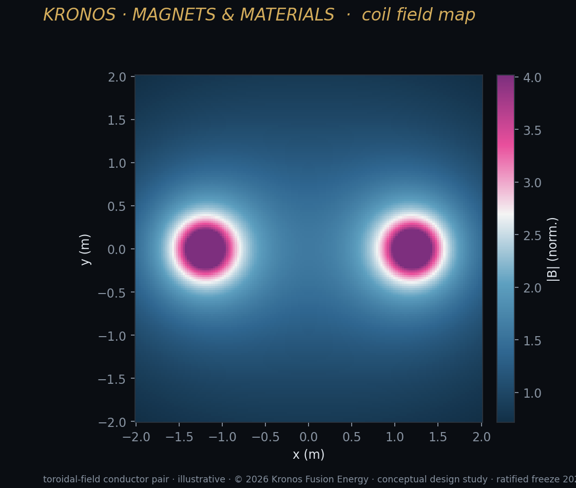
Take the breeder first, because it is the good news and it is the near-term machine. Its magnet is the toroidal-field centrepost — the load-bearing column of conductor running up the central axis of the spherical tokamak, carrying the current that makes the confining field. It runs about eight tesla on the plasma axis, with a substantially higher peak at the conductor. And the centrepost is, in the language of the study, stress-comfortable.
The reason is written directly in the boxed relation. The centrepost is a large-bore, low-current-density winding: it spreads its current over a big cross-sectional area, so the current density J_wp in the formula is modest, and the resulting hoop stress stays low across the entire operating range. Sweep the whole field space and the hoop stress runs from about 110 megapascals at the mild end up to roughly 1,834 megapascals only at the most extreme corner we tested — a 48-tesla-peak case far beyond anything we would actually build — and even that extreme sits below the reinforcement's allowable. At the honest, realisable operating point — on the order of five tesla on axis, giving roughly twenty tesla on the conductor, comfortably inside the demonstrated fusion-scale magnet record — the hoop stress is around 318 megapascals. That is not a magnet living on the edge of its structure. That is a magnet with room to breathe, and the contrast with the plug's two-to-four-thousand megapascals could not be starker: same conductor, same mechanics, same strain cap — opposite verdicts.
So if stress is not what limits the breeder's magnet, what does? Two things, and the book has already named both. The first is coil-field feasibility: if you get greedy and push the on-axis field harder — say toward ten tesla on axis, which would force something like forty tesla on the conductor, roughly twice the demonstrated record — you leave the regime that hardware has actually reached, and the honest verdict turns. We do not do that. The breeder is designed to live inside demonstrated field. The second, and the real operational limit for this machine, is neutron lifetime. The breeder burns deuterium and tritium, which means a fierce fourteen-mega-electron-volt neutron flux — its first-wall neutron load is about thirty-five times the burner plug's — and that flux slowly degrades the superconductor and everything around the centrepost. The breeder's magnet is not stress-limited. It is neutron-limited, through the narrow shielding gap the compact geometry allows. That is a materials-and-lifetime problem, which is exactly the kind of problem the breeder — whose whole near-term business is materials, not electricity — is built to confront honestly.
The burner plug — the harder magnet
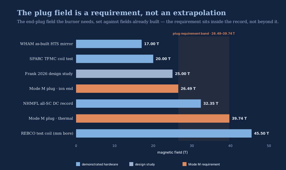
Now the burner, and here the news is harder and the honesty matters more. The burner's magnet is the high-field mirror plug — the intense field at each end of the tandem mirror that acts as the cork holding the plasma in. Its throat field is 26.49 tesla, the lower end of a self-consistent pair that runs up to 39.74 tesla at the thermal end. And the first thing to say is the counterintuitive thing: the field is not the problem. Set the plug requirement against the public record and it sits, at the ion end, below two magnets that already exist:
| Magnet | Field | Status |
|---|---|---|
| A fusion-relevant HTS mirror coil (as built) | 17.0 T | Demonstrated |
| A large-bore fusion toroidal-field model coil | 20.1 T | Demonstrated |
| Burner plug throat (ion end) | 26.49 T | Requirement |
| All-superconducting DC field record | 32.35 T | Demonstrated |
| Burner plug throat (thermal end) | 39.74 T | Requirement |
| Small no-insulation REBCO test coil | 45.5 T | Demonstrated |
At 26.49 tesla, the plug throat sits at about 0.82 times the all-superconducting record and well below the 45.5-tesla test coil; even the 39.74-tesla thermal end is only about 1.24 times the record. On the pure question of whether a magnet can reach this field, the plug is inside demonstrated hardware. Someone has already built a coil to a higher field. The pure magnetic pressure at 26.49 tesla is only about 279 megapascals, and existing magnets operate above that in small bores. The field, in other words, is retired as a worry. What is left is the bore.
The problem is the bore. A mirror plug cannot be made arbitrarily small, because the magnetic flux threading it is set by the central cell it has to plug, and flux conservation fixes a physically required bore radius of about 0.648 metres — an order of magnitude larger than a naive small-bore assumption you might reach for if you only cared about field. And now look again at the boxed relation, at that innocuous term a. Stress scales linearly with bore. A coil at 26.49 tesla with a large mandatory bore is under far more hoop stress than the same field in a small coil. This is precisely the case where a field-only scaling would have lied to you and told you the plug was easy.
Before the stress verdict, one more fact settles what is not the problem: the conductor can supply the field. In a real winding only a small fraction of the cross-section is superconductor — the rest is reinforcement, stabiliser, and insulation — so the current density that matters is the winding-pack value, the film's own critical current density multiplied by that superconductor fraction (a fill factor of only about 1.3 percent here). Even after that dilution, and after derating for strain, the achievable winding-pack current density at the plug bore is around 330 amperes per square millimetre, comfortably above the roughly 200 needed to produce the field. The conductor delivers the field across the whole plug pair with margin. (The one concession the conductor forces is temperature: at the 39.74-tesla thermal end the current density at 20 kelvin falls below the winding benchmark and recovers only when the coil is cooled to 4.2 kelvin, so the plug is a liquid-helium-temperature magnet, not a 20-kelvin one.) So the field is available and the current is available. The question — the entire question — is whether the structure survives the stress that making the field creates.
The two-dimensional finite-element analysis, run at the required 0.648-metre bore, returns numbers that do not close. The peak hoop stress lands between 2,916 and 4,253 megapascals — roughly 2.7 to 3.9 times the reinforced structure's allowable of about 1,091 megapascals. The inner-turn strain lands between 1.85 and 2.62 percent — 4.6 to 6.5 times the 0.40 percent irreversible-strain cap. These are not small overages to be engineered away with a stiffer overwrap. The winding is being asked to survive four to six times the strain that permanently destroys the conductor.
We tried the obvious remedy. You can pre-compress a winding — build in a squeeze so that the operating Lorentz load first has to work against a residual compression before it puts the ceramic into tension. The magnet paper's genuinely novel, separately filed contribution is a method for doing this well, and it has two parts. The first is a per-turn, as-built-data-driven placement of the pre-load: rather than applying one uniform squeeze computed from a worst case, you grade the pre-compression turn by turn, each turn's residual tuned from the coil's own measured critical current and as-wound geometry to offset that turn's predicted operating strain. The second is a per-coil qualification: the same as-built model certifies an operating envelope for the finished coil in place of the blanket worst-case derating the field normally applies, which recovers usable current density that a conservative derate would have thrown away. We claim the method, not any single algorithm — and it is the one part of this whole conductor story that is genuinely ours rather than public prior art applied by analysis. It transfers cleanly to the breeder, where it helps. But at the plug's physical bore it moves the peak strain by only about eleven percent. Even fully optimised — we ran a differential-evolution optimiser to convergence — the strain floors at 4.6 to 6.0 times the cap. At its physically required bore, the small-bore mirror plug coil is structurally infeasible.
I want to be careful about what that sentence means, because it is easy to read it as defeat and it is not. It is a quantified ceiling, and stating it precisely is more valuable than any optimistic hand-wave, because it names exactly what a buildable plug would require. Not a parameter tweak — a program. Four things would move the ceiling: a lower required field; a materially smaller bore, if the mirror physics ever permits one; a nested, stress-managed magnet architecture that shares the load across structures rather than piling it onto one winding; or a higher-current-density conductor that lets more of the coil cross-section be structure. Each of those is a real line of development. None of them is a knob you turn on the design we have.
Making the plug buildable: the load is real, so let the shield carry it
The bare-winding result — infeasible at the physical bore — is the conservative bound, not the last word. A follow-on design study finds the gate resolved rather than fundamental once three levers act together, and it is worth setting them out because they are exactly the "program, not a parameter" I just promised.
The first lever is to spend radial build on a lower winding-pack current density, so more of the coil's cross-section is structure and less is asked of each turn. The second is to stop treating the winding as one bonded monolith and instead build it as a mechanically segmented, pre-compressed stack — many turns each carrying a share of the load against a built-in squeeze, rather than one continuous ceramic ribbon strained as a whole. The third is the elegant one: make the neutron shield structural. The plug needs a thick shield anyway; rather than let that mass sit idle, a tungsten-based jacket is made to serve three jobs at once — radiation shield, pre-compression shell, and reinforcement. Because the shield now squeezes the winding from outside, the winding bore shrinks from 0.648 metres toward about 0.50 metres, and — since hoop stress scales linearly with bore — the stress falls in proportion. Three tiers fall out of the analysis:
| Tier | Winding bore | Shield | Strain vs. cap | Status |
|---|---|---|---|---|
| Bare winding (published bound) | 0.648 m | 30 cm, passive | 4.6–6.5× over | Infeasible |
| Stress-managed (reference) | 0.50 m | 15 cm, structural | ~0.4× (≈60% margin) | Design-study, analysis pending |
| Frontier (development target) | 0.45 m | 10 cm, advanced | ~0.4× | Levers not yet qualified |
The reference tier closes the full 26.49-tesla throat field with roughly sixty percent strain margin — a genuine, if modest, structural extrapolation over the demonstrated fusion-scale model coil. Its honest cost is that a thinner, structural shield passes more neutron flux to the coil, which pushes the design toward a demountable plug cartridge — a plug you swap on a maintenance cadence rather than one that lasts the plant's life. So the truthful state of the plug is neither "impossible" nor "solved." It is feasible pending detailed finite-element analysis: the bare winding fails, a stress-managed architecture recovers it on paper, and the confirming three-dimensional analysis is the work still to do. That is a materially more honest — and more useful — position than either the brochure's silence or the pessimist's full stop.
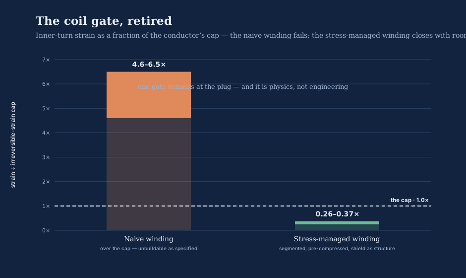
The breeder's magnet is limited by neutrons and the burner's by stress. Naming which wall each machine is actually up against — instead of hiding both behind a single reassuring field number — is the whole point of doing the analysis twice.
Quench, and the smart layer that only insulates when it must
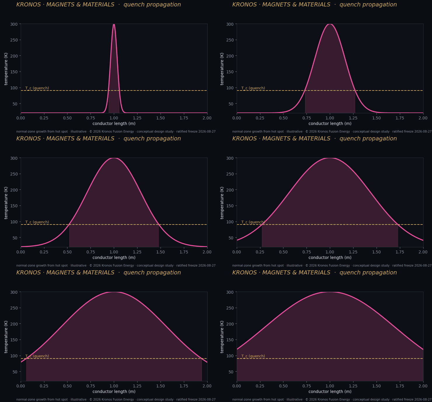
There is a second engineering reality that any account of these magnets has to face, and it is the one that keeps magnet engineers awake: the quench. A superconductor carries current with zero resistance right up until, somewhere, it doesn't — a local hot spot, a flux jump, a mechanical disturbance tips a tiny region back into the normal, resistive state. Now enormous current is flowing through a resistance, dumping heat, and if that heat is not managed the coil can destroy itself in seconds. In a coil storing the energy these do, quench protection is not a feature. It is a survival requirement.
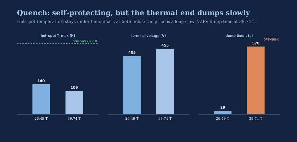
Both of our windings are designed "no-insulation" — the turns are not electrically isolated from one another, so that if a hot spot forms, current can simply detour around it through the neighbouring turns instead of forcing its way through the growing resistive zone. The analysis shows both coils are hot-spot self-protecting on this basis: the peak hot-spot temperature reaches about 145 kelvin in the burner throat and 109 kelvin at the thermal end, both comfortably below the roughly 330-kelvin self-protecting benchmark. Good. But no-insulation coils buy that safety with a cost: current also leaks between turns during normal ramping, giving these coils a charge and discharge time constant of between 2.2 and 5.2 hours. That is impractical to live with passively — you cannot wait five hours to energise a power plant — so the design requires active ramp assistance, and slow normal-zone propagation stays on the list of monitored hazards rather than solved ones.
This is where one of the conductor's seven layers earns its place: a vanadium-oxide "smart" quench interlayer. Vanadium oxide has a metal-insulator transition — it is electrically insulating at the 4-to-20-kelvin operating temperature, and switches conductive as a local hot spot heats it through its transition around a hundred-odd kelvin. The effect is a winding that behaves as insulated during normal, slow operation — curing the ramp-time problem — and as no-insulation only when and where it needs to, sharing current away from a hot spot precisely at the moment of quench. It insulates for ramping and conducts for protection, with no operator action to switch between them. We are careful to say this concept is not ours — metal-insulator-transition "smart insulation" for high-temperature superconducting coils is prior art by others, and our contribution is a reproducible model of the switching trade-space, not the invention of the idea.
The quench numbers that come out of that model are reassuring where it counts and honest where it does not. Both plug coils are hot-spot self-protecting — the peak temperature reaches only about 145 kelvin at the throat and 109 kelvin at the thermal end, well under the roughly 330-kelvin benchmark a coil must stay below to survive a quench — and the terminal voltages during a dump stay in the low hundreds of volts. The uncomfortable number is the dump time: because the no-insulation winding sheds its stored energy slowly through the turns, the discharge stretches from tens of seconds at the throat to several hundred seconds at the thermal end. That slow normal-zone propagation is not a solved problem; it is a monitored hazard we carry openly, and it is the price the no-insulation architecture charges for its self-protection.
Neutron lifetime — the limit that time imposes
The last real limit is the one that arrives slowly and cannot be designed away, only shielded against: neutron damage to the superconductor itself. Fast neutrons knock atoms out of the REBCO lattice, and here the behaviour is quietly two-faced — the tape's critical current actually rises a little at first, as light irradiation adds pinning sites, and only past a fluence threshold on the order of a few times ten-to-the-twenty-two neutrons per square metre does it turn and degrade for good. That threshold is itself an extrapolation: the published data run out around 3.9 × 10²² neutrons per square metre, and the tapes engineered with artificial pinning centres — the high-performance ones — degrade earlier than the plain tapes, so we carry the onset as an open-risk band rather than a fixed line. A magnet has a neutron lifetime the way a tyre has a tread life, and we do not pretend to know the last few thousand miles of it precisely.
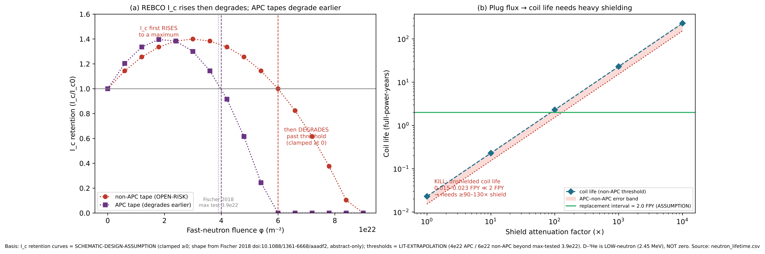
The two machines meet this limit very differently, and it maps onto the fuel each one burns. The burner plug is low-neutron by design — the deuterium–helium-3 reaction it corks produces an uncollided neutron load of only about 0.03 megawatts per square metre, at the gentle energy of 2.45 mega-electron-volts. Unshielded, even that would eat a high-field coil's life faster than you would like. But a layered shield of tungsten and borated polyethylene about 30 centimetres thick reaches the required attenuation and buys the plug a two-full-power-year coil life with margin to spare. That estimate is a one-dimensional transport calculation carrying a safety factor, and it needs full Monte-Carlo confirmation before it is settled — but the shield fits, and the physics of it closes.
The breeder is the harder case here, and this is the flip again, seen from the neutron side. Its deuterium–tritium fuel throws a fourteen-mega-electron-volt neutron flux roughly thirty-five times harder than the plug's, straight at a centrepost that the compact spherical geometry leaves little room to shield. The breeder's magnet is not stress-limited and it is not, at the honest design point, field-limited. It is neutron-lifetime-limited, at the centrepost, through the shielding gap that compactness costs you. That is a real limit, it is a materials-science limit, and it is one the breeder program takes on directly — which is fitting, because confronting fourteen-mega-electron-volt neutrons in materials is, quite literally, the breeder's day job.
What is measured, and what is not
Let me close the way the magnet paper closes, because the honesty of the ending is the point. This is a design study. Its results are reduced-order models and finite-element solutions, not experiments. Kronos has built no coil and measured no tape. Every conductor number in this chapter is public data applied to a winding; the plug and centrepost current densities are design assumptions; the neutron shield is a one-dimensional estimate; and the two field records we lean on were retrievable only from others' published work. There is no Kronos measurement anywhere in it, and we label it so at every step rather than let a reader mistake a model output for a lab result.
Because the honesty is easier to trust when it is laid out subsystem by subsystem, here is the whole verdict in one grid — each part of each machine tagged by how far its evidence actually goes:
| Subsystem | Burner plug | Breeder centrepost |
|---|---|---|
| Field capability | 26.49 T, below the record | ~20 T on conductor, realisable |
| Bore-resolved stress | 2.7–3.9× over (bare); managed on the reference tier | Under allowable |
| Winding strain | 4.6–6.5× over (bare); managed on the reference tier | Under the cap |
| Pre-load method | Per-turn, filed (novel) | Same method transfers |
| Quench | Self-protecting; slow-propagation hazard | Self-protecting |
| Neutron lifetime | Shielded to ~2 full-power-years | Centrepost-limited (the binding limit) |
| Overall | Design-study; stress-managed, analysis pending | Buildable inside demonstrated field |
The single measurement that would convert this from analysis into demonstrated fact — the highest-value next step, and the one the program has proposed to pursue through collaboration with a national laboratory — is a short-sample strain-to-delamination test on the intended conductor, run with and without the placed pre-load, to establish exactly how much margin the winding method really manages against the strain limit. Until that test is done, the strain-first stack and the per-turn pre-load method are a sound argument, not a proven one. We say so.
This is the same discipline the rest of the book runs on, and it connects the magnets back to the spine — to Q40, the fortyfold energy return, and to the honest, forty-year horizon that is the third of the three forties. The fourth-power field scaling is what makes a fortyfold return conceivable in a machine small enough to build. The magnets are how you get the field. And the reason the whole program can promise gain solved, not scaled — a design published, reproducible, and buildable in the breeder's case — is that we have been this exact about where the magnets close and where they do not. The breeder's centrepost is a magnet we can build inside demonstrated field, comfortable on stress, limited by neutrons over its life. The burner's plug is a magnet whose field is in hand but whose bore, today, over-stresses the best winding we can make — a quantified ceiling that names its own cure. High field is the path to compact fusion — the narrow road that turns a star-sized dream into a machine you can build on an industrial site inside this half-century. The magnets are what walk it, a ribbon of ceramic thinner than a hair standing between us and a hundred million degrees. And the difference between a design study and a sales pitch is that we have told you, tesla by tesla and megapascal by megapascal, precisely how far down that path each one has actually come.