Plant-Floor SCADA and HMI
The supervisory control and data acquisition surface for balance-of-plant: pumps, cryogenics, vacuum, tritium handling, and power supplies, rendered for floor operators.
Supervisory layer, not control authority
The plant-floor SCADA/HMI supervises the balance-of-plant systems that surround the fusion core: cryogenic plant for the REBCO magnets, high-vacuum pumping, gas and pellet fueling, tritium handling for the breeder, coolant loops, and the power-supply banks driving the 9.66 MA plasma current (breeder) or the 26.49 T plug (burner). It presents state and lets operators issue supervisory setpoints, but interlocks and fast trips are enforced in hardware by L1. The HMI can request a state change; it can never bypass an interlock.
P&ID-anchored screens
Screens follow the piping-and-instrumentation diagram (P&ID) topology so a floor operator navigates by the plant they already know. Each element (valve, pump, heat exchanger, feedthrough) shows live value, setpoint, mode, and health, sourced from the L2 data fabric with the same units and tags used everywhere else in the stack. Consistency of tag names across SCADA, dashboards, and incident replay removes a whole class of translation errors during upsets.
- Cryogenics: magnet temperature margins, helium inventory, cold-box status
- Vacuum: chamber pressure, pump speed, leak-rate trend
- Fueling: gas-puff servo-valve position, pellet timing queue
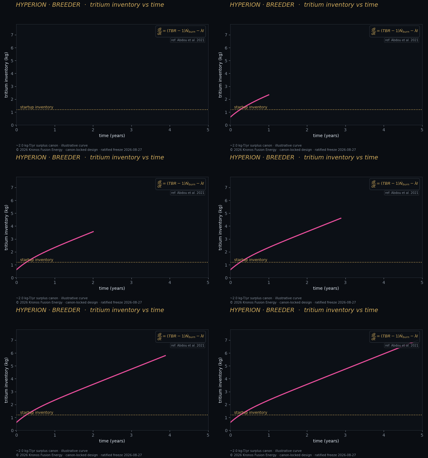
- Tritium (breeder): inventory accountancy, containment pressure, TBR context
- Power supplies: bank voltage/current, switching state, thermal margin
Modes, permissives, and mimic color
Every subsystem carries an explicit mode (off / standby / conditioning / operating / fault) and a permissive chain that shows exactly which conditions are still blocking a requested transition. Instead of a failed command silently doing nothing, the HMI names the missing permissive. Color follows the plant color grammar: energized/flowing lines are distinct from de-energized, and alarms use the reserved alert palette so an operator never confuses a normal state with a fault.
SCADA feeds the same alerting pipeline as the physics layers, so a cryo margin excursion and a plasma anomaly arrive through one rationalized alarm system — see alarm management — and are captured together for incident replay.