Mapping the Stack to the Tandem Mirror (Burner)
Layer by layer, how the same architecture instantiates on the D-3He tandem-mirror generator — from plug control to direct energy conversion.
The stack on the burner
On the burner (Aegis / MetroVolt) the eight layers keep their roles but reason about an open magnetic system. The mapping shows how the shared stack becomes a control system for a D-3He tandem mirror with a 26.49 T plug and direct energy conversion.
Layer by layer
- L0 — plug-density and ambipolar-potential design sweeps; DEC-train optimization studies.
- L1 — FPGA control of plug and throat coils; protection of the 26.49 T plug and 17 T throat.
- L2 — diagnostics resolving plug density, potential, and the 5.44% neutron fraction.
- L3 — twin modules for plug stability and potential; MPC steering flux into the DEC train.
- L4-L7 — orchestration, the plasma copilot, DEC-train dashboards, and dispatch scheduling.
The dominant loop
The burner's signature loop is plug-and-potential: diagnostics measure end-plug density and the ambipolar potential, the twin projects their evolution, the MPC agent adjusts plug heating and coil currents to hold confinement, and L1 executes within budget. Steering the escaping charged flux cleanly into the DEC train is part of the same loop.
Direct energy conversion
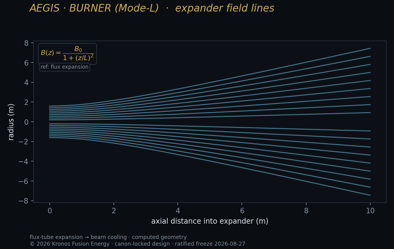
Where the breeder ends in neutrons and heat, the burner ends in a multi-modal DEC train — TWDEC, ultra-high-field MHD, and thermionic stages — that converts charged-particle energy directly. The architecture treats DEC as an orange thermal/reactor path with its own control and diagnostics, described in the DEC train.
Two housings
The burner ships in two housings: Aegis, for fixed defense installations, and MetroVolt, for data centers. Both run the identical architecture; the housing changes packaging and dispatch context, handled at L7, not the control physics.
Contrast the breeder in mapping to Hyperion; the physics is in burner control problems.